User defined types for simulation and display
Up until now, the examples have used a set of simple Simulation, Display and Line constructs without explaining how they are defined. This shows what is needed in the Dynamics block to let the user defined types to specify that they actually define a runnable simulation or settings that can be used to display results.
This means that the user can select their own names for the different parameters required for a simulation, and, more importantly, simulation and display attributes can be added to existing type definitions to make multi-faceted type definitions that can both be run on their own or as part of a larger simulation.
Example 6 shows two new elements that can be used in the Dynamics block, Run and Show as illustrated in the following user-defined type that defines a simulation:
<Parameter name="length" dimension="time" />
<Parameter name="step" dimension="time" />
<ComponentRef name="target" type="HHCell" />
<Children name="displays" type="Display" />
<Dynamics>
<StateVariable name="t" dimension="time" />
<Run component="target" variable="t" increment="step" total="length" />
<Show src="displays" />
</Dynamics>
</ComponentType>
The 'component' attribute of the Run element specifies which parameter of the type contains the reference to the component that should actually be run. The 'step' and 'increment' attributes specify the parameters that hold the timestep and total runtime. The 'variable' attribute is for future use - at present, the independent variable is always 't'.
A Run element can be added to the Dynamics block in any type definition to make it independently runnable.
Running a simulation without any output is rarely much use, so there are two futher elements that can be included in the Dynamics block: Show and Record. The 'src' attribute of the Show element points to the components that should be shown. These in turn can contain other Show elements but eventually everything pointed to by a Show element should contain one or more Record elements. These specify what will actually be sent as output. They have the path to the variable as the 'quantity' attribute, its scale as the 'scale' attribute and the line color for plotting.
The following two types show one way that these can be combined to allow the user to express a display object containing one or more lines.
<Parameter name="timeScale" dimension="time" />
<Children name="lines" type="Line" />
<Dynamics>
<Show src="lines" scale="timeScale" />
</Dynamics>
</ComponentType>
<Parameter name="scale" dimension="*" />
<Text name="color" />
<Path name="quantity" />
<Dynamics>
<Record quantity="quantity" scale="scale" color="color" />
</Dynamics>
</ComponentType>
Once these have been defined, a component can be constructed that uses them as follows:
<Simulation id="sim1" length="80ms" step="0.05ms" target="hhcell_1">
<Display timeScale="1ms">
<Line id="V" quantity="v" scale="1mV" color="#0000f0" />
<Line id="Na_q" quantity="NaPop/geff" scale="1nS" color="#f00000" />
<Line id="K_q" quantity="KPop/geff" scale="1nS" color="#00f000" />
</Display>
</Simulation>
When run, this produces the output shown below:
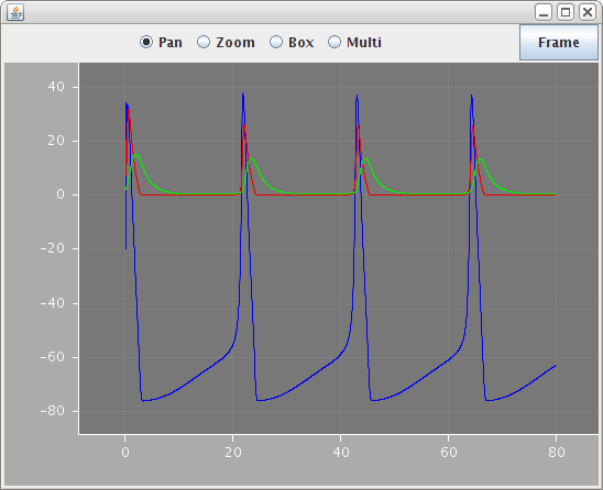
Note how the scale attributes are set to 1mV and 1nS for the different lines so that they show up on the same axes.