Kinetic schemes
The existing components provide everything necessary to define types that allow a model to specify a kinetic scheme (Markov model). The missing ingredient is the Dynamics element to actually expresses how instances of the components develop through time.
First then, the following definitions can be used to express ion channel models where the the channel state is represented by an occupancy vector among a number of distinct states with rates for the transitions between states.
<Parameter name="power" dimension="none" />
<Parameter name="deltaV" dimension="voltage" />
<Children name="states" type="KSState" />
<Children name="transitions" type="KSTransition" />
</ComponentType>
<Parameter name="relativeConductance" dimension="none" />
<Dynamics>
<StateVariable name="occupancy" dimension="none" />
<DerivedVariable name="q" value="relativeConductance * occupancy" />
</Dynamics>
</ComponentType>
<Fixed parameter="relativeConductance" value="0" />
</ComponentType>
<Fixed parameter="relativeConductance" value="1" />
</ComponentType>
<Link name="from" type="KSState" />
<Link name="to" type="KSState" />
<Requirement name="v" dimension="voltage" />
<Exposure name="rf" dimension="per_time" />
<Exposure name="rr" dimension="per_time" />
</ComponentType>
<Parameter name="conductance" dimension="conductance" />
<Children name="gates" type="KSGate" />
<Exposure name="g" dimension="conductance" />
<Dynamics>
<DerivedVariable name="fopen" dimension="none" select="gates[*]/fopen" reduce="multiply" />
<DerivedVariable name="g" exposure="g" dimension="conductance" value="fopen * conductance" />
</Dynamics>
</ComponentType>
This says that a gate can contain any number of states and transitions. A state has an occupancy variable, and a transition has links to two states giving the source and target states for the transition.
The transition element here is an abstract element because it doesn't provide a Dynamics block but just specifies what quantities transitions should privide via the two exposures. One of the most useful forms of transition is a damped Boltzman equation which can be parameterizd as follows:
<Parameter name="vHalf" dimension="voltage" />
<Parameter name="z" dimension="none" />
<Parameter name="gamma" dimension="none" />
<Parameter name="tau" dimension="time" />
<Parameter name="tauMin" dimension="time" />
<Constant name="kte" dimension="voltage" value="25.3mV" />
<Requirement name="v" dimension="voltage" />
<Dynamics>
<DerivedVariable name="rf0" dimension="per_time" value="exp(z * gamma * (v - vHalf) / kte) / tau" />
<DerivedVariable name="rr0" dimension="per_time" value="exp(-z * (1 - gamma) * (v - vHalf) / kte) / tau" />
<DerivedVariable name="rf" exposure="rf" dimension="per_time" value="1 / (1/rf0 + tauMin)" />
<DerivedVariable name="rr" exposure="rr" dimension="per_time" value="1 / (1/rr0 + tauMin)" />
</Dynamics>
</ComponentType>
Given these definitions, we can express a couple of simple channel models that use kinetic schemes. There is nothing special about these models. They are just examples used in PSICS that produce spikes (albeit rather unnatural looking ones) when used together.
<KSGate power="1" deltaV="0.1mV">
<KSClosedState id="c1" />
<KSClosedState id="c2" />
<KSOpenState id="o1" relativeConductance="1" />
<KSClosedState id="c3" />
<VHalfTransition from="c1" to="c2" vHalf="-35mV" z="2.5" gamma="0.8" tau="0.15ms" tauMin="0.001ms" />
<VHalfTransition from="c2" to="o1" vHalf="-35mV" z="2.5" gamma="0.8" tau="0.15ms" tauMin="0.001ms" />
<VHalfTransition from="o1" to="c3" vHalf="-70mV" z="1.1" gamma="0.90" tau="8.0ms" tauMin="0.01ms" />
</KSGate>
</KSChannel>
<KSGate power="1" deltaV="0.1mV">
<KSClosedState id="c1" />
<KSOpenState id="o1" />
<VHalfTransition from="c1" to="o1" vHalf="0mV" z="1.5" gamma="0.75" tau="3.2ms" tauMin="0.3ms" />
</KSGate>
</KSChannel>
This has all been done with the existing components. They allow types to be defined for expressing kinetic schemes, and models can be expressed that use these types, but there is nothing so far that says that the model actually is governed by a kinetic scheme. In particular, there is an "occupancy" state variable in each state element for which there is no governing equation and the rates generate "rf" and "rr" quantities that are not unused anywhere.
What is needed is a new element in the Dynamics block to link these together and say that the rates apply to the changes of occupancy among the state elements. This is done by adding a KineticScheme element to the Dynamics block for a gate as follows (this now shows the full definition of the KSGate element):
<Parameter name="power" dimension="none" />
<Parameter name="deltaV" dimension="voltage" />
<Children name="states" type="KSState" />
<Children name="transitions" type="KSTransition" />
<Dynamics>
<KineticScheme name="ks">
<Nodes children="states" variable="occupancy" />
<Edges children="transitions" sourceNodeName="from" targetNodeName="to" forwardRate="rf" reverseRate="rr" />
<Tabulable variable="v" increment="deltaV" />
</KineticScheme>
<DerivedVariable name="q" dimension="none" select="states[*]/q" reduce="add" />
<DerivedVariable name="fopen" exposure="fopen" dimension="none" value="q^power" />
</Dynamics>
</ComponentType>
The new part here is the KineticScheme element and its children Nodes, Edges and Tabulable. The Nodes element says which elements in the parent container are goverened by the scheme, and which variable in those elements represents the relative occupancy.
The Edges element is a little more complicated. It has to say not only which elements define the transitions, but how the fields in the transitions map to things the scheme knows about. For a transition in a kinetic scheme, you need to know which state the transition comes from, which it goes to, and how fast it goes. It is possible (as here) that a single transition defines both directions, in which case it must also say which variable in the target objects provides the reverse transition rates. This is what the last four attributes of the Edges element do.
The Tabulable element is a temporary convenience for implementation purposes. In this case it says that the rates depend only on v and that the transition matrices can be cached an reused on a grid of spacing deltaV rather than recomputed every time. This is not used in the 0.2.1 version of the interpreter.
Note that the KineticScheme element doesn't say anything about what the outputs are. All it does is control the occupancy state variable in the state elements. The interpretation of these quantities is specified in the normal way with the two DerivedVaraible declarations. No special elements are needed in the scheme itself.
To actually use these models we need cell and population elements to link them all together. There is nothing new here - it all works just as for HH channels. The rest of the example4.xml file is:
<ComponentRef name="channel" type="KSChannel" />
<Parameter name="number" dimension="none" />
<Parameter name="erev" dimension="voltage" />
<Requirement name="v" dimension="voltage" />
<Dynamics>
<DerivedVariable name="channelg" dimension="conductance" select="channel/g" />
<DerivedVariable name="geff" value="channelg * number" />
<DerivedVariable name="current" value="geff * (erev - v)" />
</Dynamics>
</ComponentType>
<Parameter name="capacitance" dimension="capacitance" />
<Children name="populations" type="ChannelPopulation" />
<Parameter name="injection" dimension="current" />
<Parameter name="v0" dimension="voltage" />
<Dynamics>
<OnStart>
<StateAssignment variable="v" value="v0" />
</OnStart>
<DerivedVariable name="totcurrent" dimension="current" select="sum(populations[*]/current)" />
<StateVariable name="v" dimension="voltage" />
<TimeDerivative variable="v" value="(totcurrent + injection) / capacitance" />
</Dynamics>
</ComponentType>
<ChannelPopulation channel="na1" number="600" erev="50mV" />
<ChannelPopulation channel="k1" number="180" erev="-77mV" />
</KSCell>
<Network id="net1">
<XPopulation id="kspop" component="kscell_1" size="1" />
</Network>
<Simulation length="80ms" step="0.07ms" target="net1">
<Display timeScale="ms">
<Line quantity="kspop[0]/v" scale="mV" color="#ff4040" />
</Display>
</Simulation>
When run, this produces:
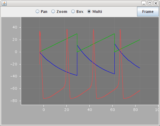
There are clearly some initialization issues but the basic Dynamics is the same as the PSICS version of this model.